Case study for fluidic simulation use
Once pilot-scale experiments were carried out, at first to prove the feasibility and later to optimize a granulation process in the laboratory, a large-scale plant had to be designed for a specified higher production capacity. Based on the gas velocities within the process chamber and in the discharge system, which were experimentally determined, as well as the specified temperature conditions, at first the geometry of the machine was computed as a 3D model.
According to the knowledge from the laboratory tests, the process and classification air flow rates as well as the pressure conditions in the upper area of the process chamber were specified as marginal conditions. The distribution plate was defined as porous medium and its real pressure drop characteristic based on measurements on the material used in practice was stored in the simulation system. Also the fluid bed area itself was modeled as porous medium with isotropic differential pressure behavior. The corresponding pressure drop characteristic was theoretically computed based on known fluid bed models. This approach made multi-phase modeling dispensable reducing the expenses for model set-up and numerical computation considerably.
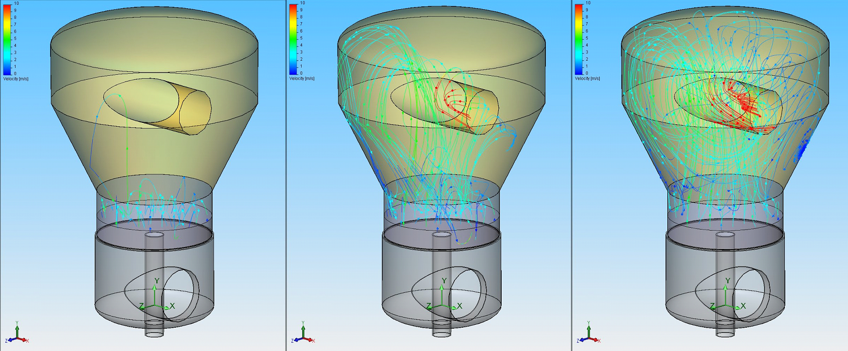
To model real temperature conditions the fluid bed volume was also defined as volumetric heat sink as heated process air conveys its energy depending on the liquid amount to be evaporated and is thus cooled. This changes the gas density, for example, which has to be taken into account for simulation. Further, representations of gas flow lines within the apparatus are helpful. They show very clearly flow redirections as well as direct influences of the apparatus geometry.
One of the main objectives of the computations was to determine the required dimensions of expansion and calming zones. Such upper areas within the fluid bed apparatus are mainly used to pre-separate particles entrained from the fluid bed.
For this, simulation studies were carried out for which particles of different size were introduced in the velocity field. The upper side of the fluid bed volume was used for this as starting level as the process air entrains particles from there as well. Particle paths were computed taking a non-ideal reflection on the apparatus walls into account. For this, identical quantities of particles with three different sizes were introduced and computed.
It can be seen that larger particles remain within the apparatus and, starting from a certain diameter, a portion of smaller particles come out of the apparatus together with the exhaust air. Further, finer particles are more likely to be entrained by the process air flow and flow back within the expansion area close to the wall. It can also be seen that the air flow directed towards the exhaust air entrains circulating particles.
By changing the machine’s geometrical dimensions as well as the exhaust air tube’s location it is possible to influence the internal separation behavior in a well-aimed manner. This separation behavior depends on the particle size and on the machine’s geometry and size. Fluidic simulation offers the opportunity to examine such dimensional factors in a systematical manner and thus to improve the functional reliability of the apparatus.
However, when using such simulation computations great importance has to be attached to the methods and models used. Normally, massive simplifications are integrated or the models are only valid and applicable for specific applications. Application fields and results to be expected should be exactly defined before selecting simulation software and models to be used.
By considering appropriate system limits valid results can be obtained with single-phase models for thinned gas-solids systems, for example. This was shown in this contribution on the example of the separation behavior within the upper part of a fluid bed apparatus. However, the behavior of the fluid bed as a whole can also be integrated as marginal condition in single-phase systems making it possible to model geometric dimensions of complex fluid bed machines as well.
Modeling of higher particle concentrations as they occur in the area of the fluid bed itself, for example, is only possible with multi-phase models which also take into account the interactions between the individual phases. When doing so, a considerably higher expense has to be expected so that such simulations are often restricted to the actual process space.





 Copyright by Glatt
 Copyright: Glatt
 Copyright: Glatt
 Copyright: Hüthig GmbH